Select Models Yard ModelsActionsOpen Yard Editor...
The parallel buffer is the area parallel to the quay where AGVs wait for orders. You configure the parallel buffer in Yard Editor.
To configure the parallel buffer:
Create the parallel buffer stack block (on page 1)
Set up the Yard Path Model for the parallel buffer (on page 1)
The Drive Time Manager (DTM) uses the vertices and yard path defined for a parallel buffer to calculate the distance between two waypoints. If the vertices are not defined accurately, the drive time estimates are not accurate.
Connect the parallel buffer to the water-side transfer zone (on page 1)
Connect bollards to parallel buffer (on page 1)
To create the parallel buffer stack block
The following procedure details only what needs to be configured specifically for a parallel buffer. For more detailed information about the Yard Block fields, see Yard Block form (on page 1).
In Yard Editor, create a new stack block:
Select ModelsYard ModelsActionsOpen Yard Editor...
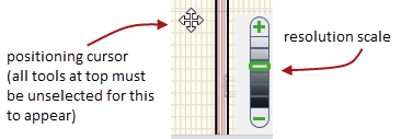
Use the resolution scale and the positioning cursor to zoom in on the point in the yard where you want to add the parallel buffer.
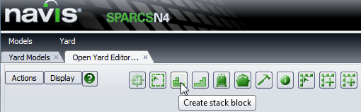
Click the Stack Block tool:
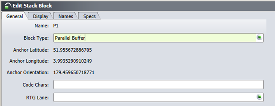
Under the General tab, for Block type, select Parallel Buffer, and fill out the rest of the fields.
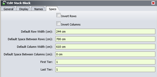
Under the Specs tab, set First Tier and Last Tier to 1.
When you Save, the form closes and N4 creates the new stack block.
It now appears in the Yard Blocks view (Yard Yard Blocks) and as a colored rectangle on the graphical map in the location you specified in the Yard Editor.
Right-click on the block and select Add Yard Sections.
Add a yard section for every parallel buffer slot.
In the Add Yard Sections form, the First Column and Last Column fields should be set to 1.
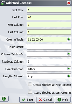
Click Save.
Set up the Yard Path Model for the parallel buffer
To set up the yard path model for the parallel buffer, you create ingress and egress vertices by drawing a yard path parallel to the parallel buffer block.
Select the Draw yard vertex tool  .
.
Click on Parallel buffer "V2" Vertex, then draw a line from V2 to the parallel buffer, as shown below:
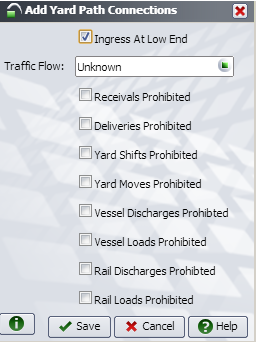
You will see dialog asking whether you want an ingress or egress connection. Click Egress.
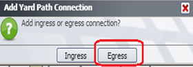
The Add Yard Path Connection form displays.
For Label, enter PB1.
For Ingress Vertex, enter V1, and for Egress Vertex, enter V2.
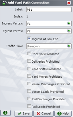
When finished, click Save.
In the yard model, check that the Ingress and Egress are connected to the parallel buffer.
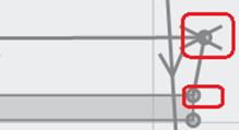
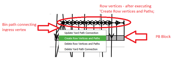
Right-click on either the ingress/egress bin path and choose Create Row Vertices and Paths.
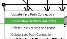
You will see the following dialog:
Don't change any of the values. Click Save. You will see multiple vertices, as shown in the encircled area below:
To connect the parallel buffer to the water-side transfer zone
Select ModelYard ModelsActionOpen Yard Editor...
For each waterside transfer zone, connect to the closest parallel buffer zone slot, as follows:
Select the Yard path model tool  .
.
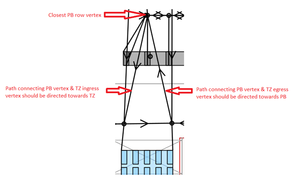
For the transfer zone ingress vertex, create a path starting from the parallel buffer directed towards the transfer zone.
For the transfer zone egress vertex, create a path starting from the transfer zone directed towards the parallel buffer.
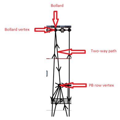
To connect bollards to parallel buffer
Select ModelYard ModelsActionOpen Yard Editor...
For each bollard, connect to the closest parallel buffer row vertex, as follows:
Select the Yard path tool .
Connect the bollard vertex to the parallel buffer vertex.
Make the path two-way.
Complete this process for the barge-side parallel buffer.